In many ways. For me it started with some research on truss designs and how they impact their materials. Then I compared my material (balsa) with the research and chose a K-truss. Then I sketched out my ideas in Inventor and later produced it as a physical project. A lot of constraints and criteria are taken into account when developing a project like this.
What makes a good bridge design
The ability to withstand loads that are able to support their own weight, tenfold- if not thousandfold.
2. What are the materials
Required:
Balsa wood
Elmers/wood glue
Wax paper
Straight scissors or exacto knife
Graph Paper
Optional:
Cardboard or foam board
Straight pens
3. Define our problem & criteria/constraints
Our problem is that we need to make the most structurally efficient model truss bridge.
Criteria
Minimum clear span of 8"
Maximum bridge length of 12"
The bridge deck must extend the entire length of the bridge and maintain a "vehicular roadway" without any obstruction (2" wide x 2" height)
The bridge deck shall be the full width of the vehicular roadway and extend the entire length of the bridge's longest dimension
The bridge deck shall be level
The bridge deck shall be constructed using a single solid balsa wood sheet. The balsa wood sheet used for the deck must be 1/16" thick.
The bridge shall be a minimum of 2" wide and must allow a 2" x 2" cube to be passed along the length of the bridge ("vehicular roadway) with no obstructions.
Gussets, dowels, mitered joint connections are allowed, but only at the joint areas. They can be no thicker than 1" and no larger than 1/2" squared in area.
Individual members shall be constructed of a single piece of balsa wood
The bridge must allow a 3" x 3" cube to be passed beneath it at mid-span, measured while the end supports are resting on a flat surface
The bridge must be freestanding
There must be a 1/2" hole at mid-span in the bridge deck to allow for testing. There should be no obstructions below the hole that would prevent the passage of the testing rod.
A 1 1/2" wide x 3" long x 1/2" thick loading plate will be posititioned over the hole in the deck at midspan and placed directly on the balsa wood deck.
A testing rod will fit through the 1/2" hole in the balsa wood deck and attach to the loading plate.
Bridges will be loaded initially with only the bucket and testing apparatus. Dry sand will be added after the initial loading until the bridge collapses.
Constraints
Laminated members are not allowed.
The bridge must not weigh more than 30g.
The bridge deck shall not be curved or arched.
A bridge may not be coated with any material.
There will be no use of steel bars to elevate the plate above the deck.
The bridge shall contain no member wider than 1/8" nor deeper than 1/8".
4. Required reasearch terms
Tensile Strength: Tensile strength is the complete maximum amount of stress that a material can undergo, stretched or pulled, before breaking.
Fracture Strength: Fracture strength is the material's ability to resists failures. It is designated according to the mode of applied force (tensile, compress, or bending).
Fatigue Strength: Fatigue strength is the highest amount of stress you can apply to a material without it breaking upon repeated cycles.
Creep: Creep in engineering is the deformation of a material at a higher temperature with a constant stress. It is time-dependent.
Hardness: Hardness is the material's level of resistance before it undergoes deformation. Harder materials tend to be quite brittle.
Sheer: Sheer is the deformation of an object through forces acting on points of the body. It can be colinear or planar.
Truss: Trusses are assemblieas of members such as beams and steel, connected at nodes, which create a rigid structure based off of triangles (cant sheer). They are very strong.
Aerolastic flutter: Flutter occurs when the wind speeds up to a point that the aerodynamic forces on the deck cause it oscilate, causing it to vibrate and bend.
Superstructure: A superstructure is the extension of a structure above the baseline. A simple example is the area above the foundation of the house.
Span: Span is the distance between the supports used for bridges. It is also a word used with any hanging wire (such as power lines and telephone cables). It is when the bridge starts to droop from its own weight.
Load: Load is the force an engineered structure has to be designed to resist. They cause stress and deformations in structures that you need to fix.
Substructure: The substructure is the antithesis of superstructure. It is the downwards extension of the structure, into the ground. In the house example it would be the foundation.
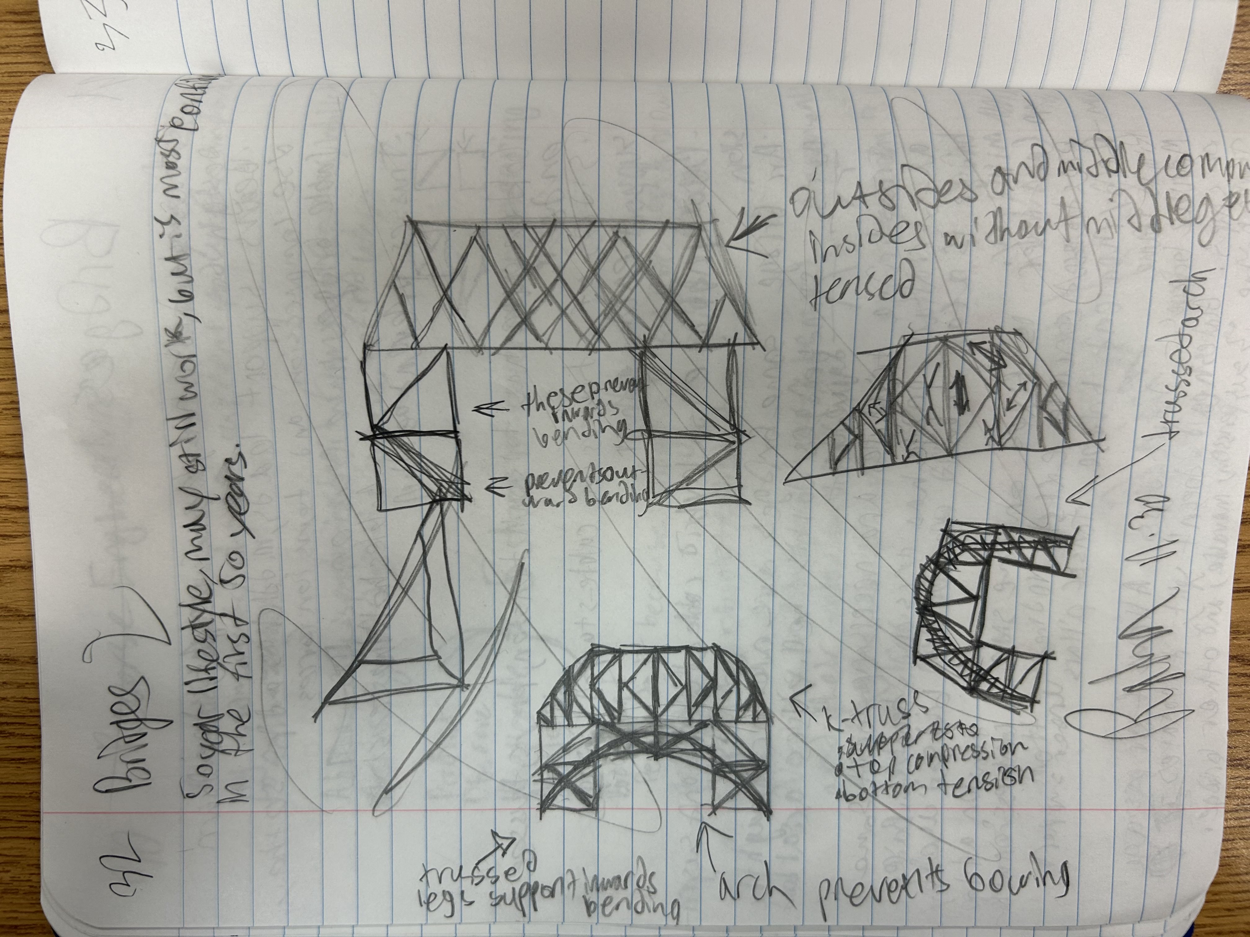
5. Designs + pros/cons
Bridge Designs 1 and 2
Pros for 1:
K-Truss
Trussed legs
Arch can prevent bowing
Cons for 1:
Might bend inwards
Arch may be detrimental
Pros for 2:
Trusses prevent inward bending
Double-warren helps structure
Cons for 2:
Superstructure trusses may be too heavy and hurt the design
Might not carry a ton of weight
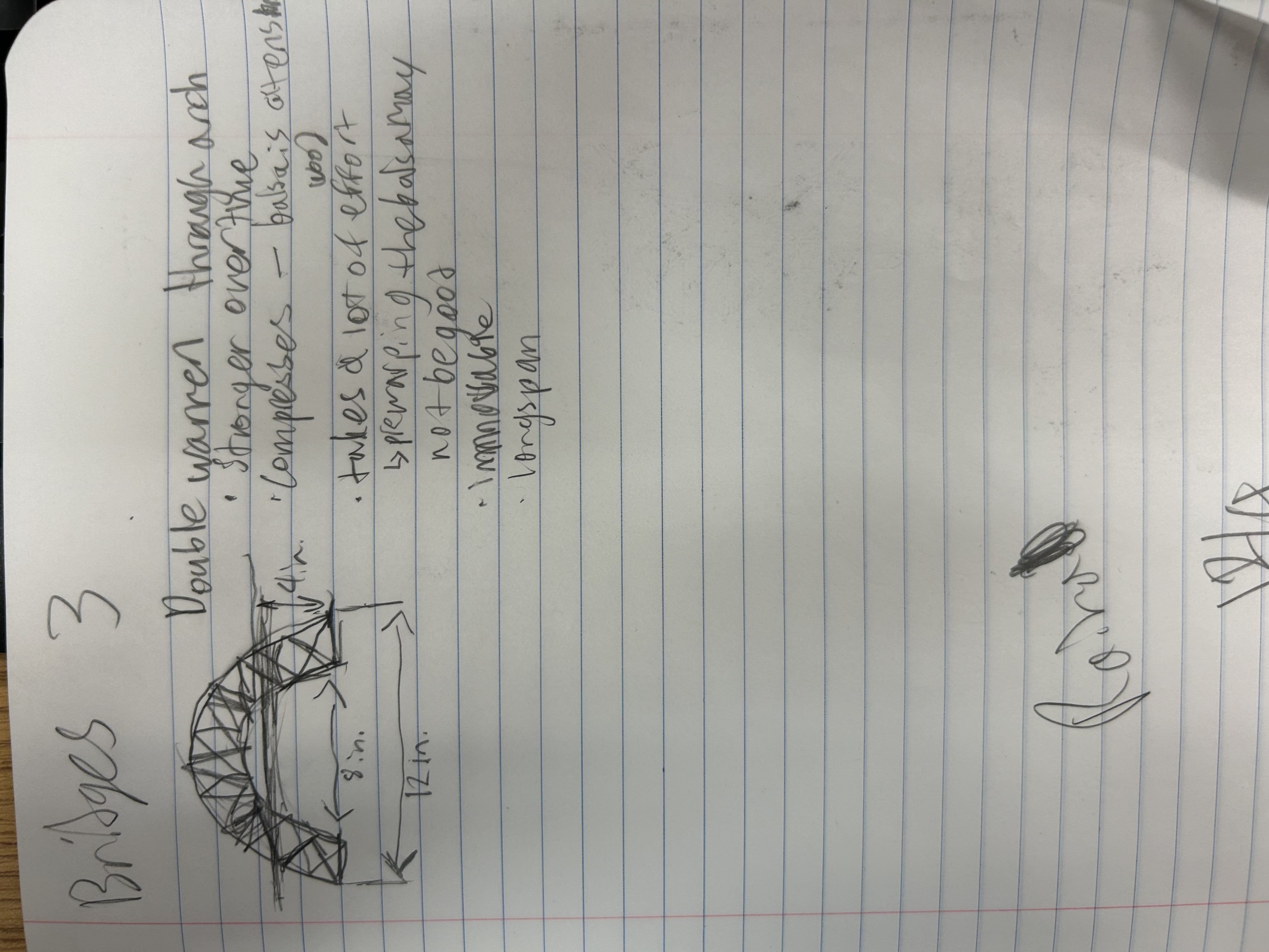
Bridge Design 3
Pros for 3:
Stronger over time
Long Span
Lot's of effort pays off
Cons for 3:
Compression isn't balsa's strong suit
Immovable
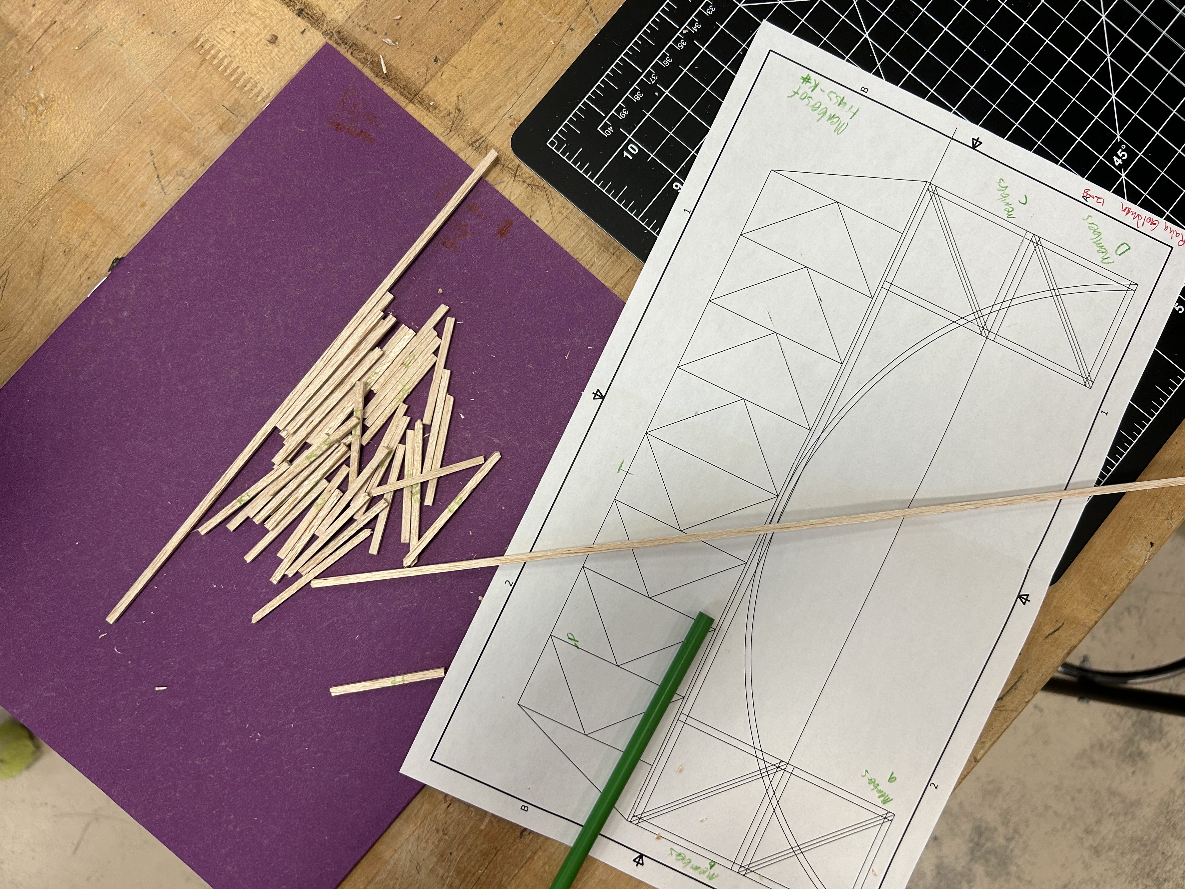
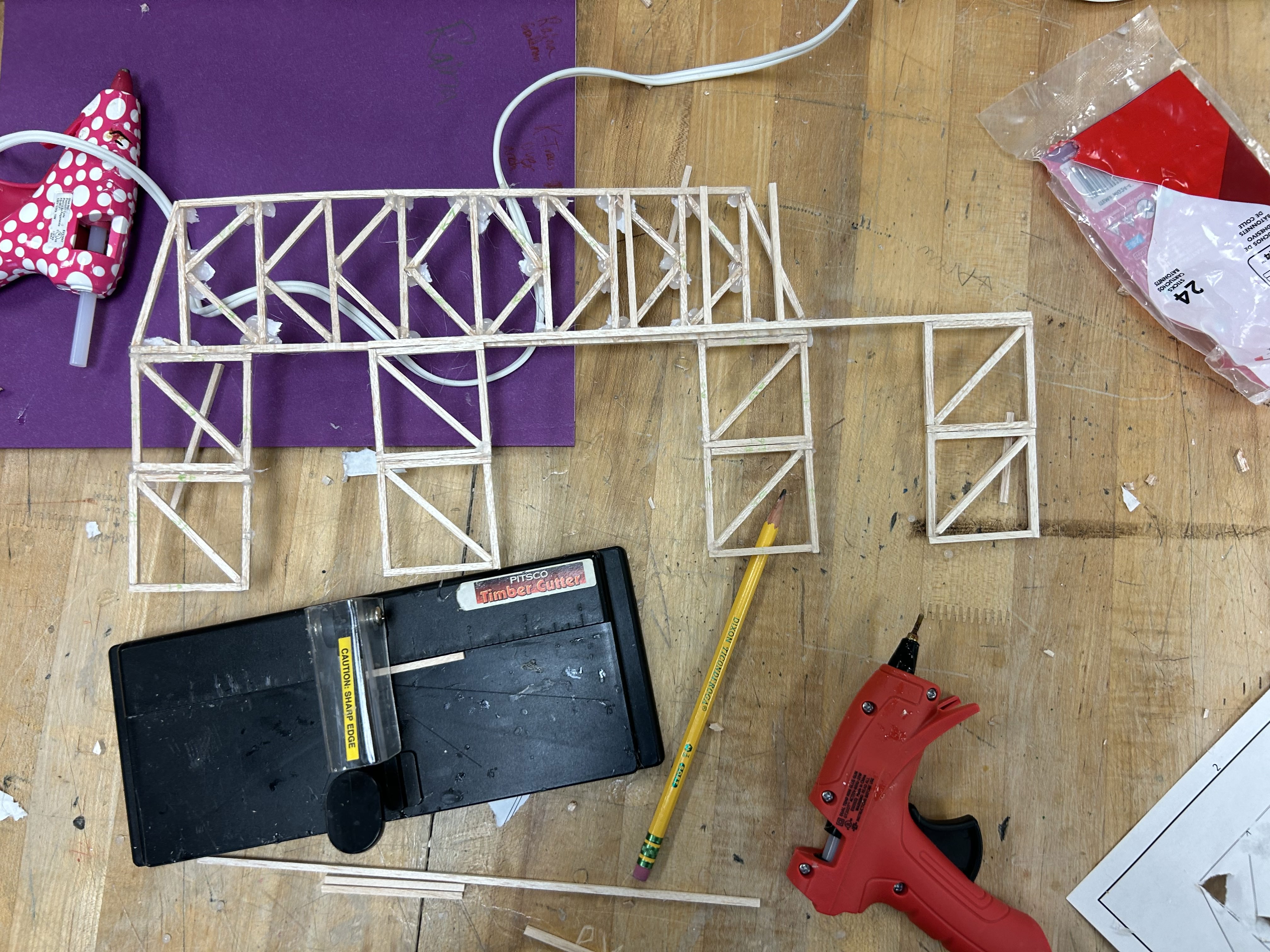
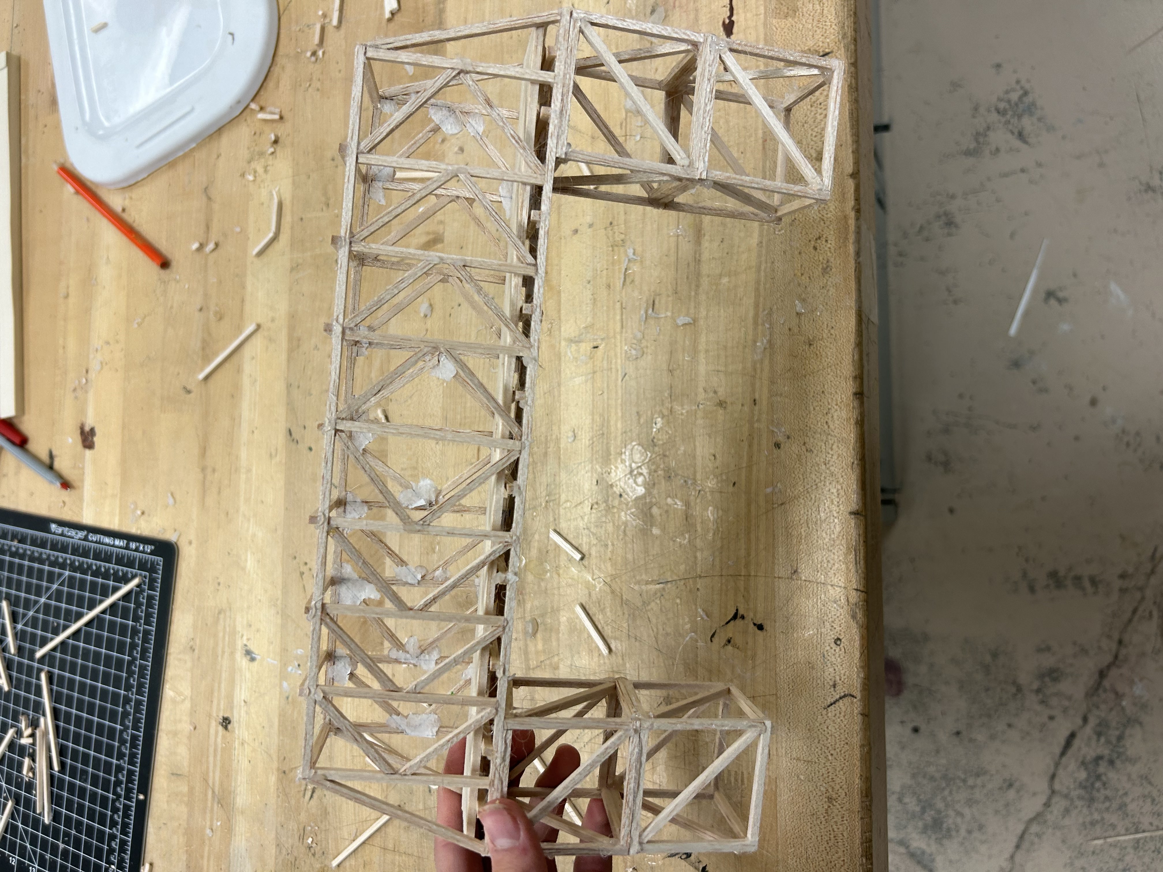
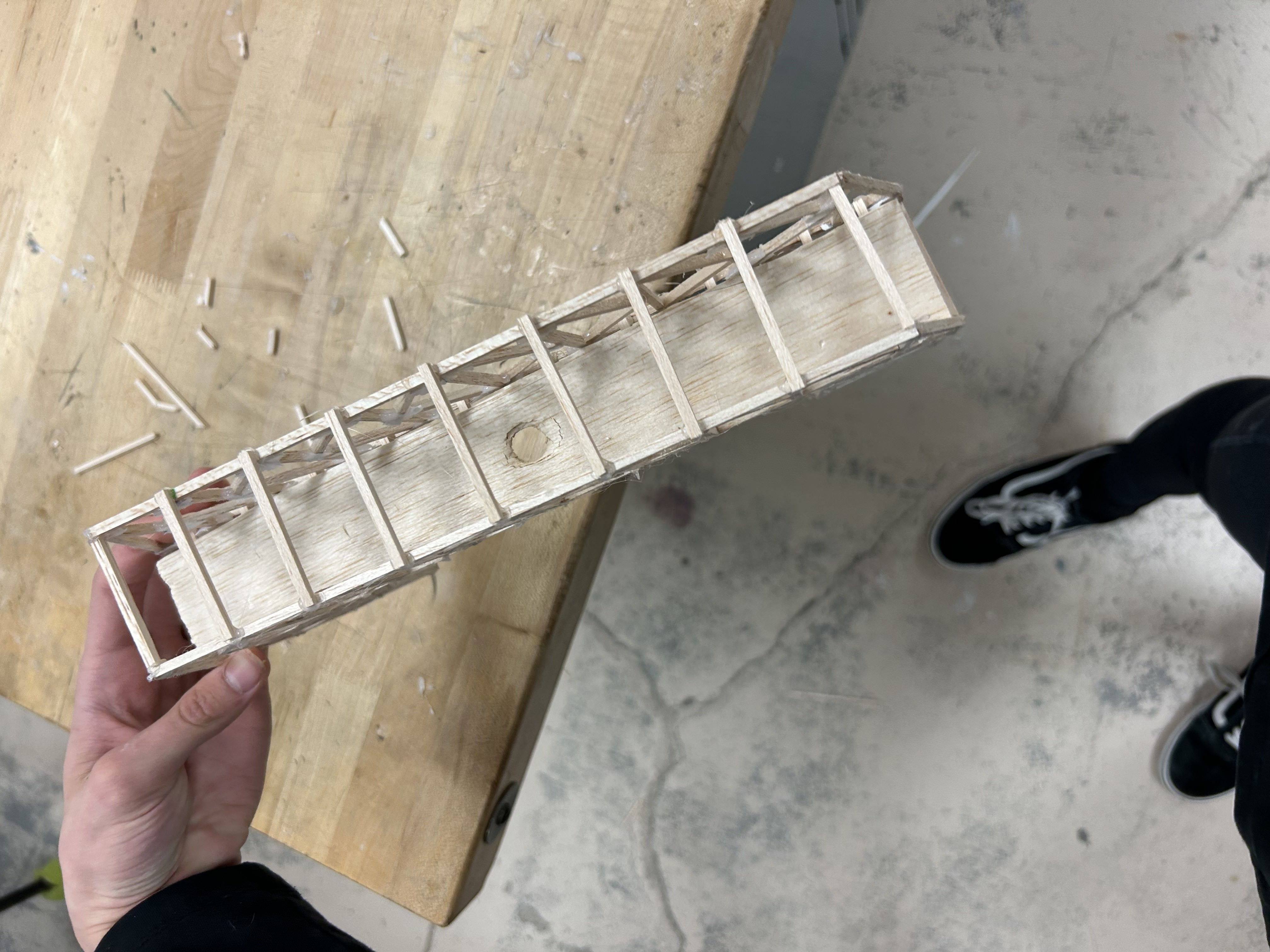
6. Documentation of physical prototype
Build process:
Beginning Construction.
It has begun.
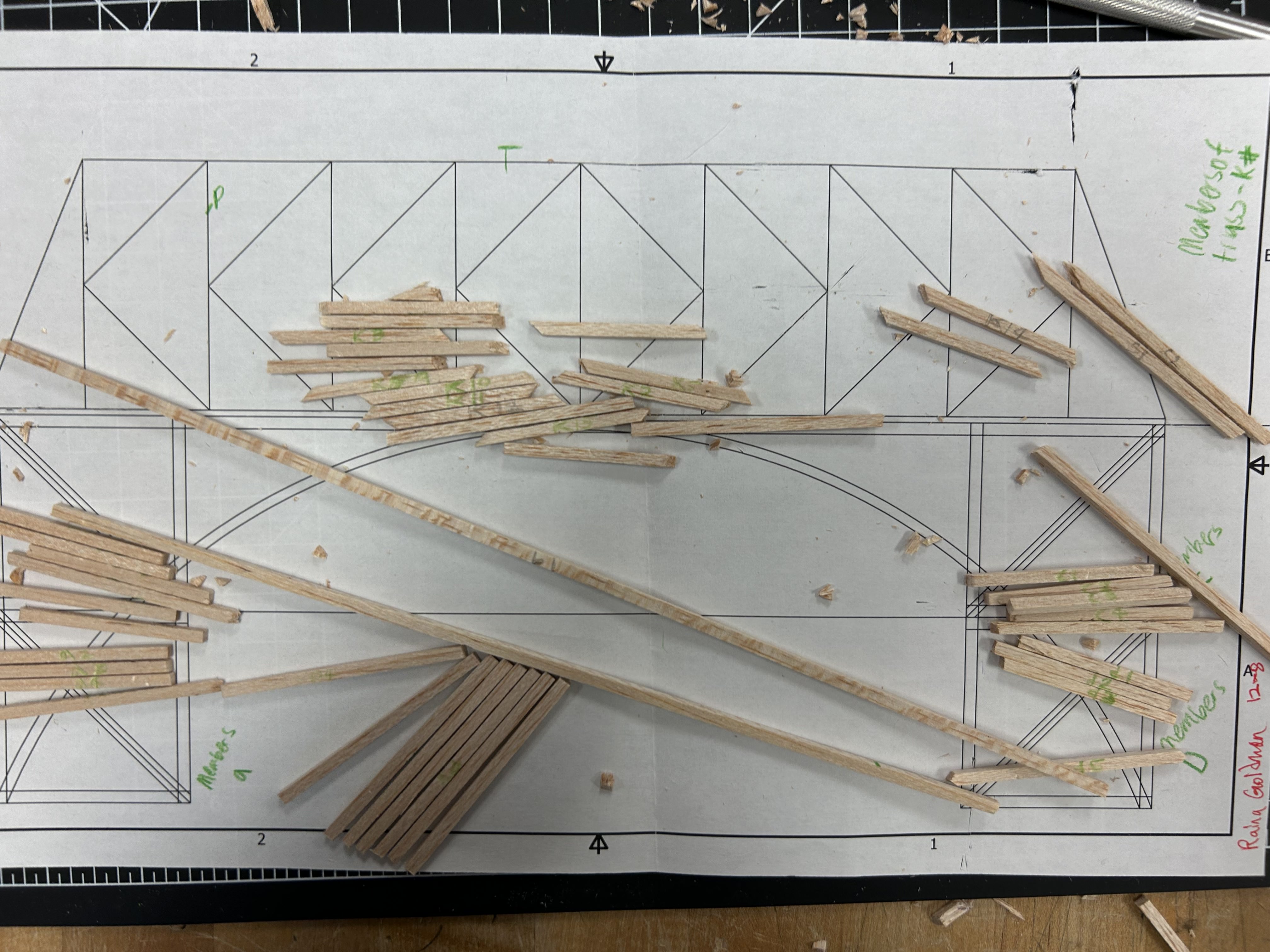
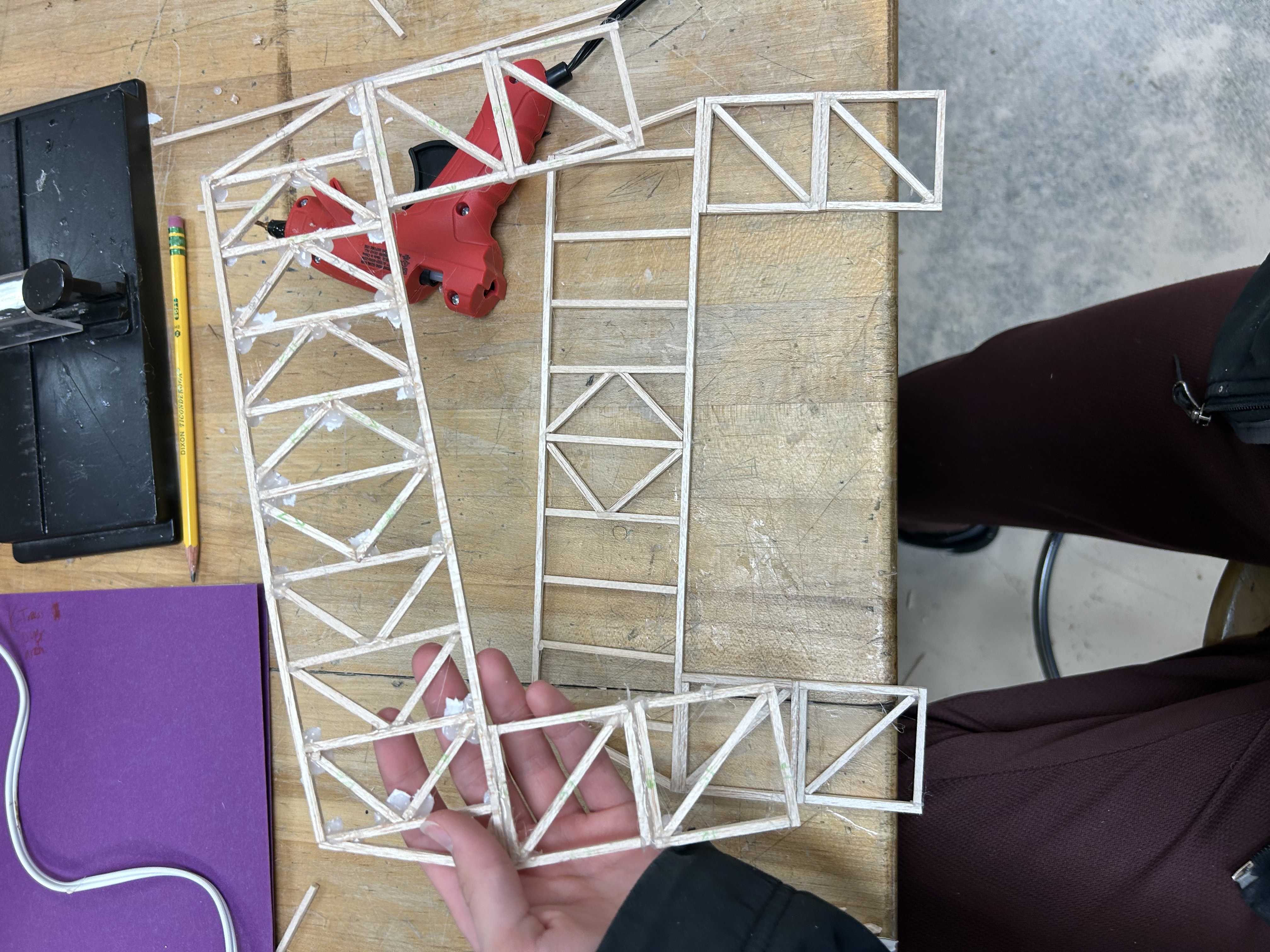
Finishing cuts for first frame.
We shall continue
Begin second frame construction.
First frame done.
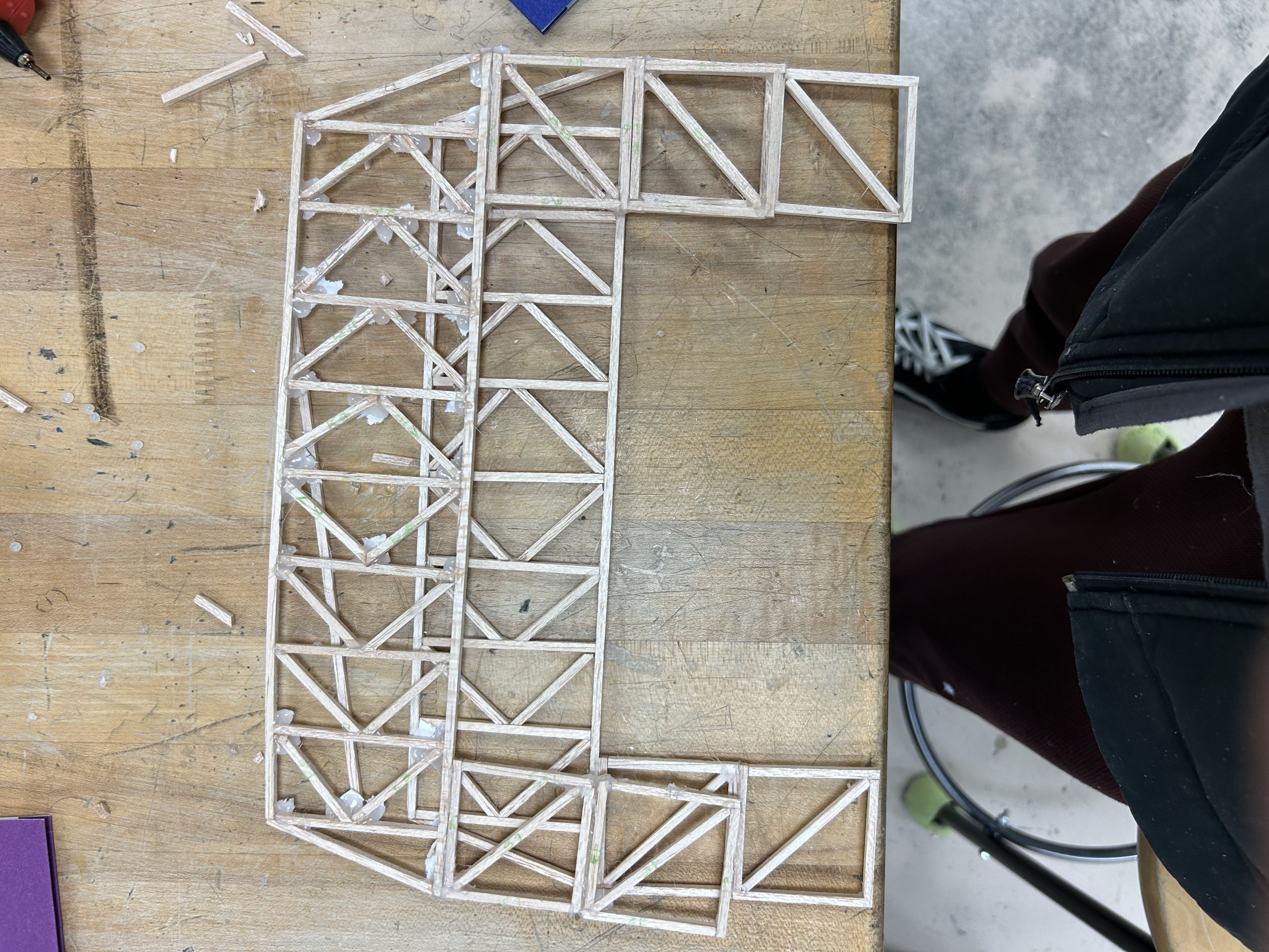
Finishing up second frame construction.
We shall continue
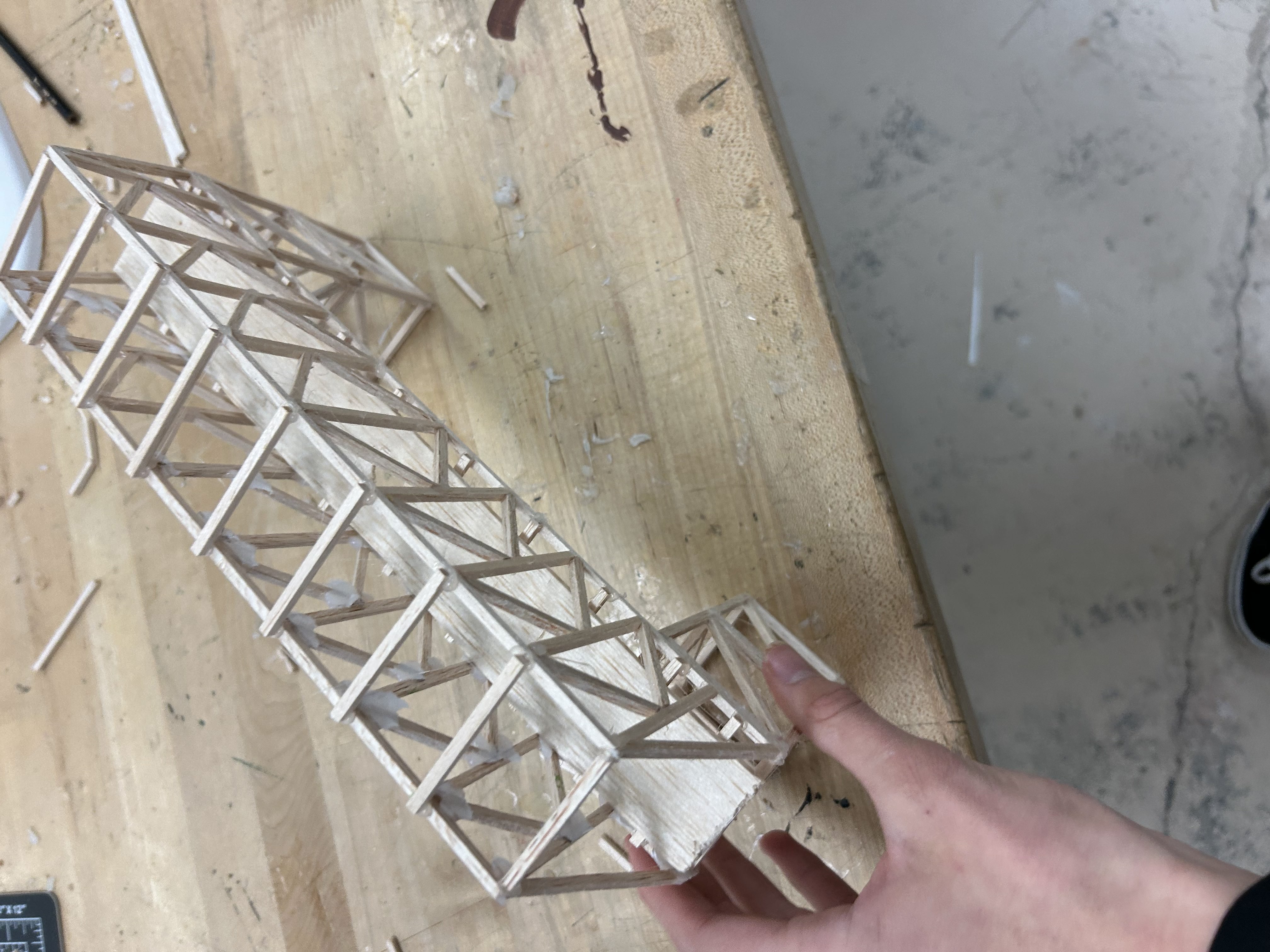
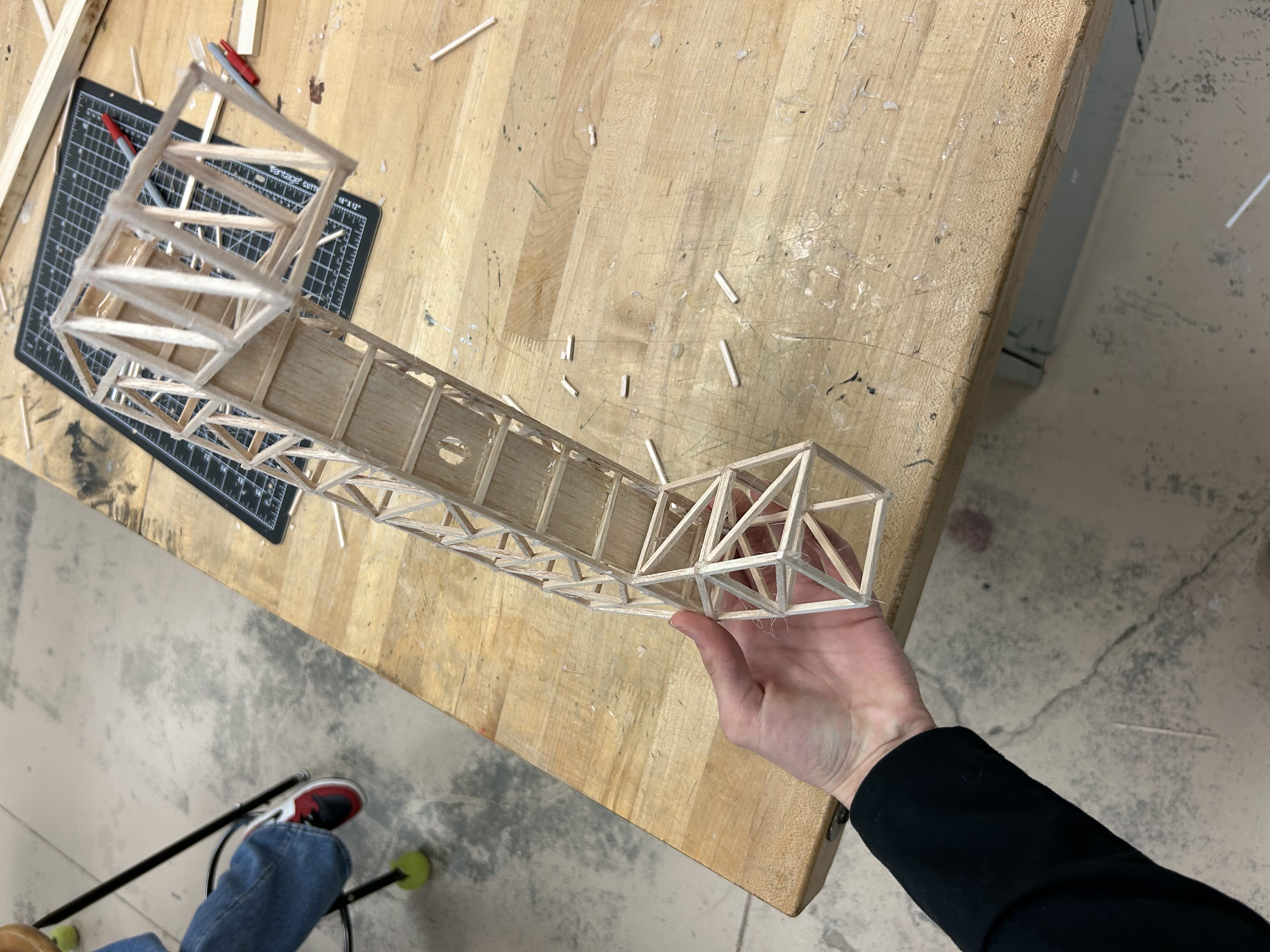
Beginning final construction.
It has begun.
Now that we have finished the frames, we will begin construction.
Constructed bridge 1.
We shall continue.
Constructed bridge 2.
We shall continue
Constructed bridge 3.
We shall continue.
Constructed bridge 4.
We shall continue
Time to test.
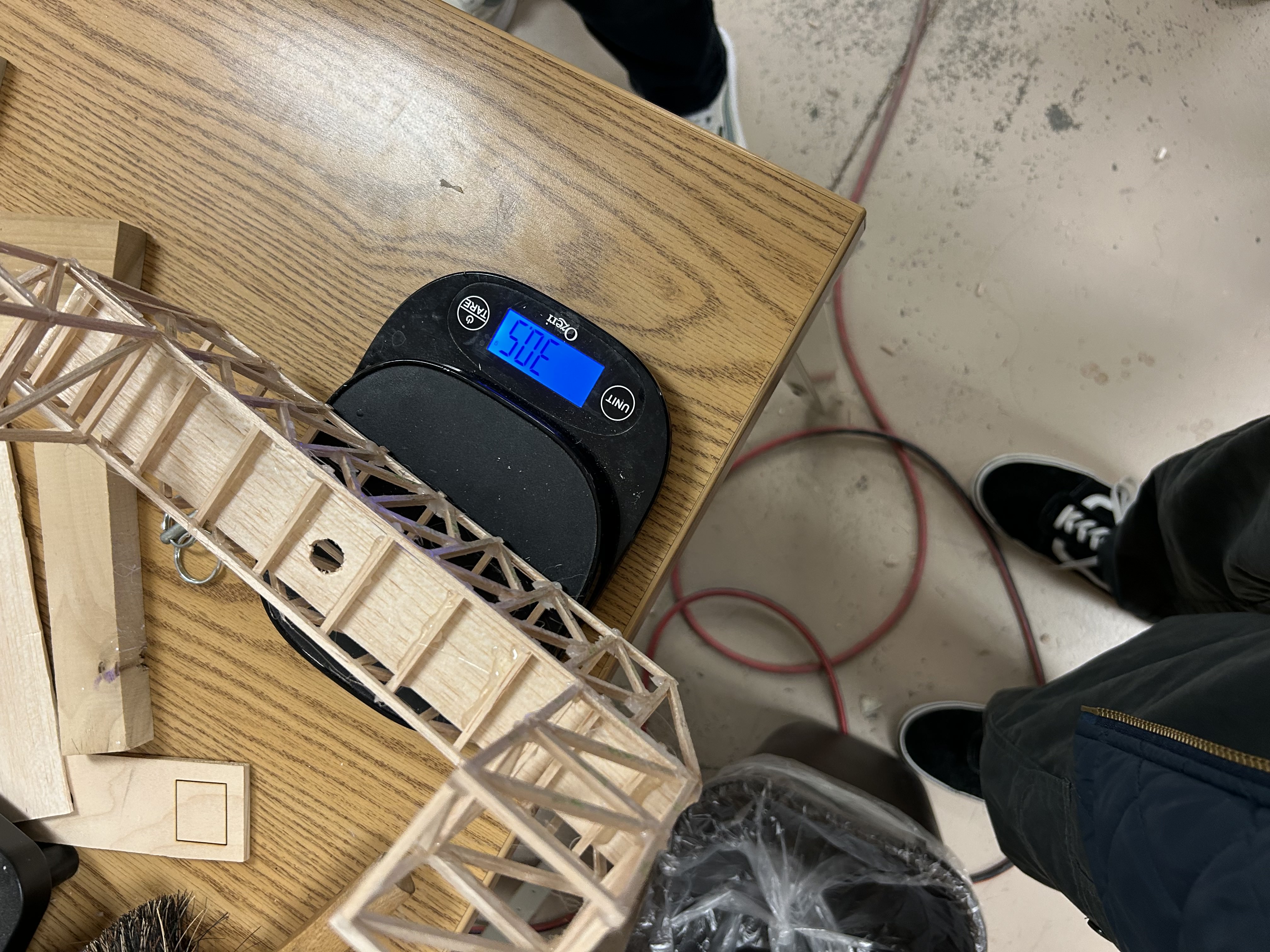
7. Overview and analysis
Weighing my bridge!
We got 30.5 grams.
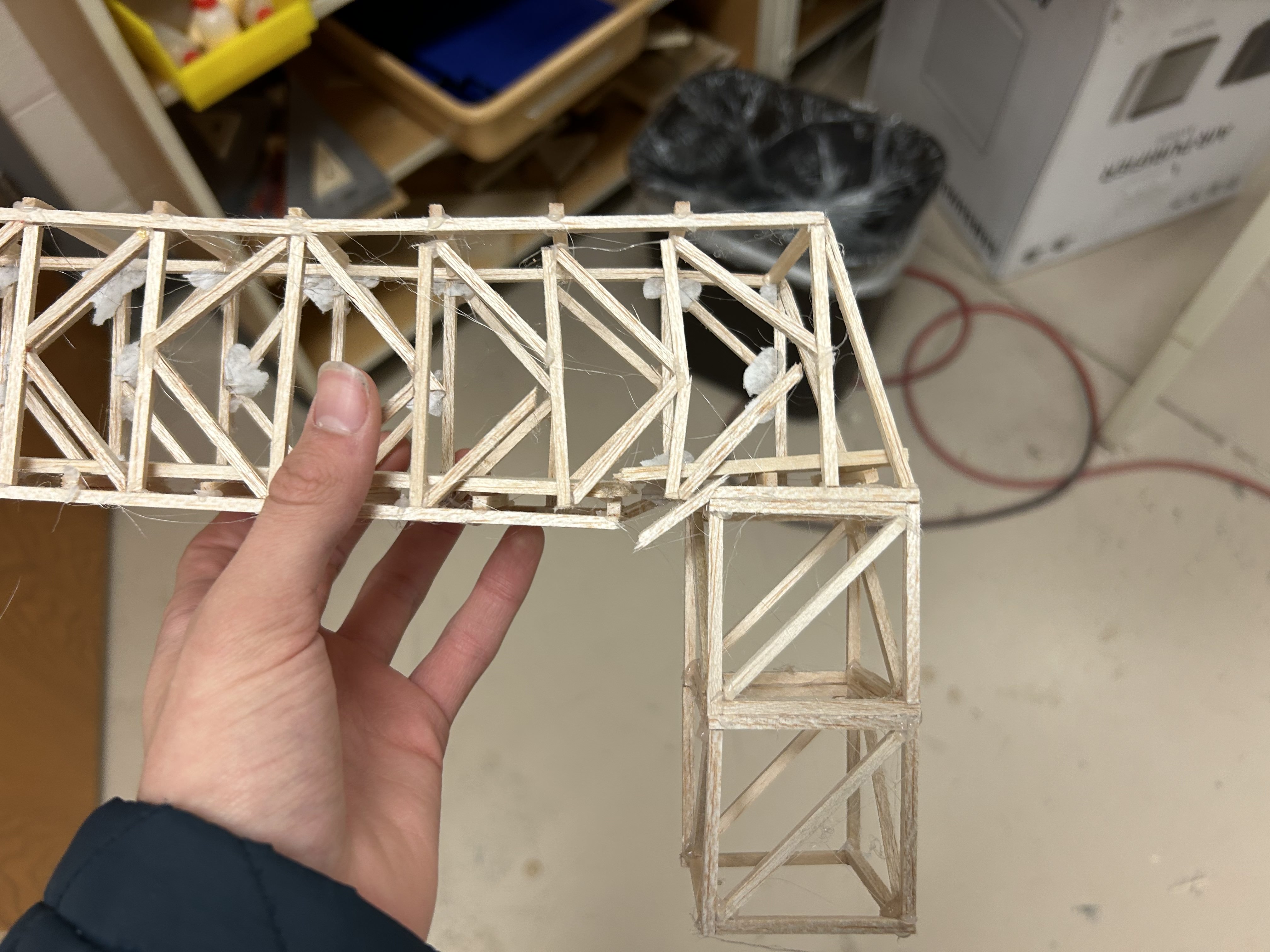
A large image of the fractured bridge.
It didnt break too badly.
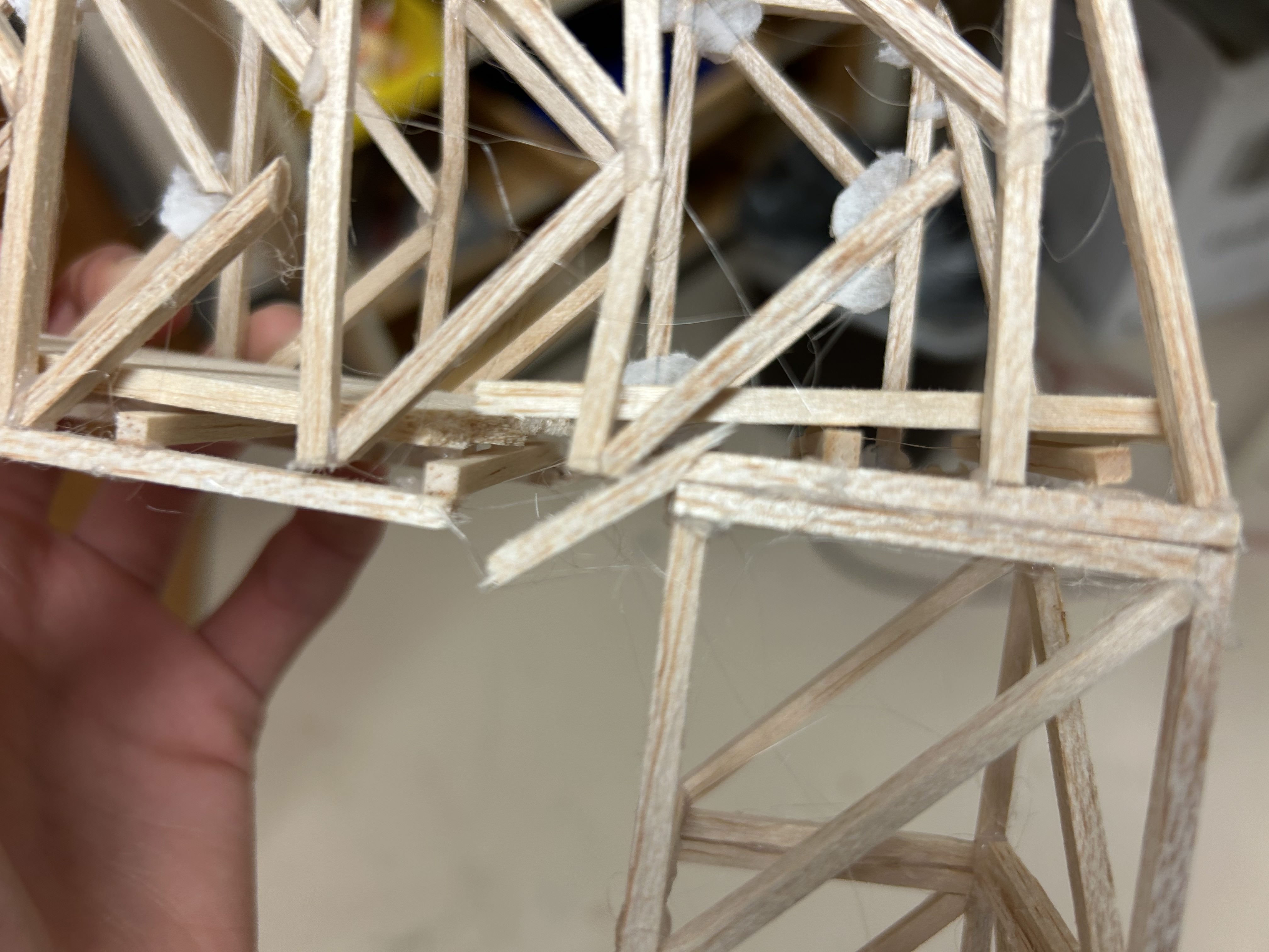
A zoomed in image of the main fracture.
However, the main fracture was pretty bad.
Analysis and failures.
To begin, some statistics. My bridge weighed 30.5 grams and was able to carry well over 400 times its own weight, collapsing at 32 lbs or 14.5 kg. Specifically, it held 454.59 times its own weight. The major failure that eventually caused the bridge’s collapse was the cooling of glue before the deck was installed and a truss appearing to break off easily. When installing the deck onto the bridge, I put some bars to hold onto it and create some small but strong joints. However I could not figure out a way to install the deck so I just put down some glue across the bars but one half cooled first while I was adding to the other side. This resulted in hard beads of glue to be stuck underneath the wood instead of a thin layer of glue that adhered the deck and the bars. As the bridge began to bow due to the design of the K-truss, it pulled up on the deck and bars and caused the plastic-y glue beads to put pressure on the deck leading to a fracture, that fracture also went the other direction and caused the bars underneath to fracture. In the same location, the truss over it started to disconnect and break. As those fractures grew, the pressure on the rest of the bridge led to some smaller cracks and deformations across the whole of the bridge. By the time the major fractures hit critical they merged with smaller fractures and caused the whole side to dip and fail.
Incidents
Major incidents:
Wasting 2 days on a single frame.
Glue beads drying too quickly on the deck supports.
Leg of frame 1 was missaligned so I had to make a new one and reattach it.
Not using every tool. The table-based cutter was useful in the second half.
Not making the internal dimensions 2x2, but instead 1.75.
If your browser doesn't support the h.265 codec, or if it's glitching out, try opening the video in VLC. Download the video here.